How to reveal a button or a contact closure from a remote place without using new cables and with no service cost?
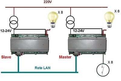
By mean of the new system Line Repeater we will be able in replicating the status of 8 input lines over a remote device using simply the Ethernet.
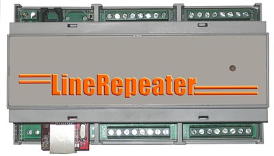
System overview
We have very often the need of knowing a contact status or revealing the button closure even in places far away from the actual position of the signal source.
In these cases we are forced to make use of long cables or of complex systems, maybe difficult to be configured, able to transfer the needed information from the source to the finale place.
When the contact lines become more than one or two, then the situation becomes even more complex and difficult to be managed.
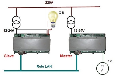
The Line Repeater system allows solving this problem in a vary easy way, transmitting with reliability the input lines status between two twins devices connected together on the Ethernet.
In fact, the input lines closure of the Master device will cause the closure of the related output lines of the Slave device, so allowing the status control.
Simplicity and quickness
The way of placing on the field the Line Repeater is characterized by great simplicity:
very few parameters to be configured and reliable working are surely the main features of the system.
The system working is based, as you can se in the previous picture, on two twins devices connected together by a TCP/IP link, both over LAN or Internet.
One of them will be configured as the Master and the other as the Slave.
Another mode is available too, it is called Cross and it will be described in the following of the article.
The device configured as the Master unit is the one where connecting the contact to be revealed.
The Slave device has the task of replicating the Master inputs status on its relays.
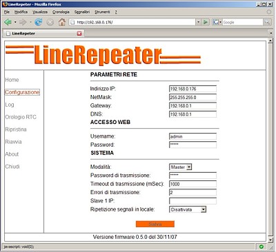
The main parameters of the equipments to be configured are simply their own IP address and the Master/Slave modes:
once these ones are set, the system is ready to start.
All the configuration and the device control are performed by integrated Web interface.
In the following picture the configuration interface is shown:
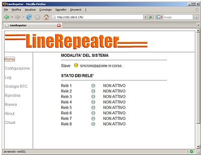
In the following picture you can see also the Web panel showing the device status:
As mentioned before, there is also a third working mode, called Cross.
In this mode, both the devices act as Master and Slave at the same time.
So the activation of an input on one of the two device will cause the activation of the related output relay on the other one.
Electric Features
The main hardware features of the system are listed in the following:
- Extended voltage range power supply 12-24V AC/CC
- Ethernet Interface 10Mbit
- 8 Inputs configurable one by one both photocoupled or voltage free
- 8 Outputs with relays 48V/2A
- 1 signalling LED in two color light
- 1 reset button
As mentioned, the inputs may be configured independently one by one so allowing the simultaneous connection of signalling contacts of different kinds.
Extended Features
Not only the configuration described in the previous section, where the Slave unit replicates the Master inputs status, but it is also possible to enable other modes that ma be useful in many application.
The first mode (Immediate Replication) allows replicating immediately on the Master outputs the input lines status: this way, also local signalling may be enabled, not only the remote one on the Slave unit.
The second mode (Replica Slave) executes the same operation, replicating on the Master outputs the status of its input lines. The difference is in the way this activation is realized: in fact, in this case the Master unit sends a message informing about the inputs status change to the Slave, then it receives this notification, it changes according its outputs and it sends back a new message to the Master about reception performed; only at this moment the Master unit can modify its outputs according to its own inputs status. In this way a local replica of the input lines status is achieved but also with the guarantee about the reception of this information by the Slave unit.
Of course both these modes are not compliant with the Cross configuration since in this case both inputs and outputs of each unit are engaged.
Application examples and customization
The system may be used for transporting remotely any kind of voltage free input as well as input with voltage up to 24V.
For example signals coming from the opening of accesses and gates may be driven into guard boxes or control rooms in wide areas or halls, as well as signals of industrial machines fault over lightened panels or switches activation and sensor over home automation control unit.
Moreover if public IP addresses are available, then this kind of input signal transfer may be executed over the Internet between places very far away, so retrieving an actual channel of remote control just for free.
On request, extended versions of the firmware are available allowing a single Master unit to control several Slave units so replicating the signals in more than one place simultaneously.
Download
 User Manual (only Italian available): LineRepeater_V130.pdf User Manual (only Italian available): LineRepeater_V130.pdf
Segnala questo articolo:
Tags: - Networking - Telecontrollo -
|

 Articles
  Hardware
  Master Boards
  Line Repeater: how to control inputs remotely using TCP/IP

 Articles
  Hardware
  Master Boards
  Line Repeater: how to control inputs remotely using TCP/IP